Produktbeskrivning
Welded Metric Roller Drive Conveyor Chain CZPT Plastic Stainless Steel Duplex Cast Iron Plate Flat Top Finished Bore Idler Bushed Taper Lock Qd Sprocket
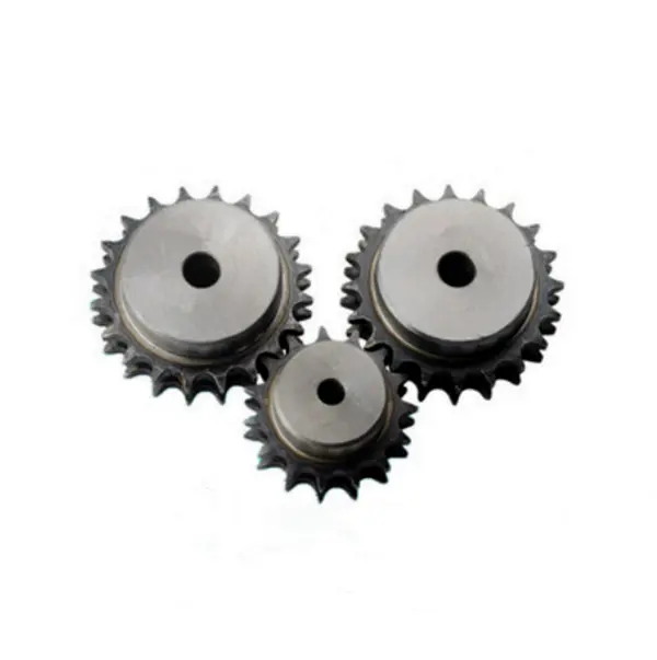
Standard sprockets:
|
||||||||||||||||||||||||||||||||||||||||||||||||||||||||
Customization process :
1.Provide documentation: CAD, DWG, DXF, PDF,3D model ,STEP, IGS, PRT
2.Quote: We will give you the best price within 24 hours
3.Place an order: Confirm the cooperation details and CZPT the contract, and provide the labeling service
4.Processing and customization: Short delivery time
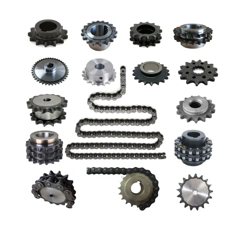
Related products:
Our Factory
If you need to customize transmission products,
please click here to contact us!
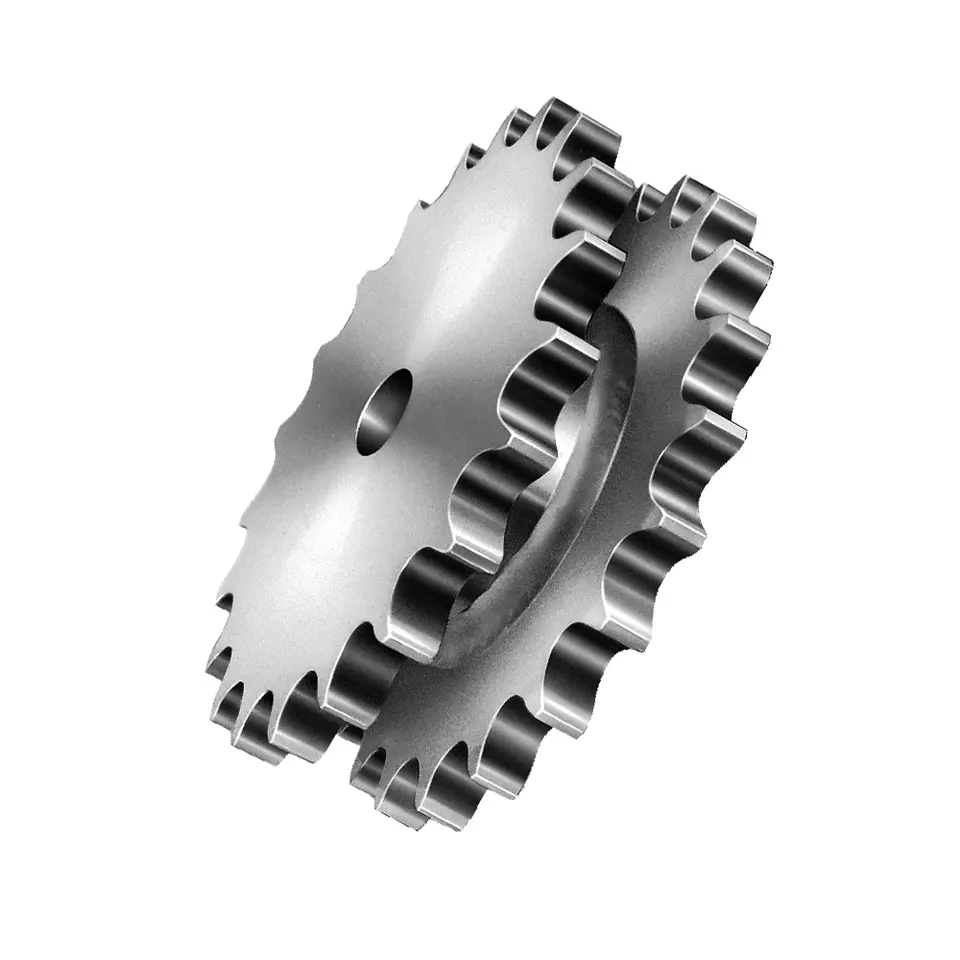
Chain Sprockets:
Company Information:
| Standard Or Nonstandard: | Standard |
|---|---|
| Ansökan: | Motor, Electric Cars, Motorcycle, Machinery, Marine, Agricultural Machinery, Car |
| Hardness: | Hardened Tooth Surface |
| Manufacturing Method: | Cut Gear |
| Toothed Portion Shape: | Spur Gear |
| Material: | Custom Made |
| Samples: |
US$ 9999/Piece
1 Piece(Min.Order) | |
|---|
Säkerställa korrekt inriktning mellan ett hjul och motsvarande kedjehjul
Korrekt inriktning mellan ett hjul och motsvarande kedjehjul är avgörande för att hjulets kedjesystem ska fungera smidigt och effektivt. Felaktig inriktning kan leda till ökat slitage, buller och minskad prestanda. Här är några steg för att säkerställa korrekt inriktning:
- Använd precisionskomponenter: Se till att båda hjuldreven är högkvalitativa, precisionstillverkade komponenter som uppfyller de erforderliga specifikationerna. Genom att använda välbearbetade komponenter uppnås bättre uppriktning.
- Kontrollera axeljustering: Se till att axeln eller skaftet som hjuldreven är monterade på är rak och korrekt inriktad. Eventuell feljustering i axeln kan leda till feljustering av hjuldreven.
- Korrekt montering: Säkerställ att hjuldreven är ordentligt och korrekt monterade på axeln eller skaftet. Använd lämpliga fästelement och åtdragningstekniker för att förhindra rörelse eller förskjutning under drift.
- Kontrollera parallellitet: Hjulhjulets axlar ska vara parallella med varandra. Mät avståndet mellan axlarna på flera punkter för att verifiera parallell uppriktning.
- Använd justeringsverktyg: Uppriktningsverktyg, såsom laseruppriktningssystem, kan användas för att exakt rikta in hjulet. Dessa verktyg kan hjälpa till att identifiera och korrigera feljusteringar effektivt.
- Kontrollera spänning och spännarens inriktning: Om en spännare används i systemet, se till att den är korrekt inriktad och att kedjan eller remmen har rätt spänning. Felaktig spänning kan orsaka feljustering.
- Regelbundet underhåll: Implementera ett regelbundet underhållsschema för att kontrollera och justera justeringen vid behov. Regelbundna inspektioner kan hjälpa till att identifiera och åtgärda justeringsproblem innan de orsakar allvarliga problem.
- Övervaka prestanda: Håll koll på hjulets kedjesystems prestanda. Ovanliga ljud, vibrationer eller tecken på slitage kan tyda på feljustering och bör undersökas omedelbart.
Korrekt inriktning är avgörande för hjuldrevssystemets långsiktiga prestanda och tillförlitlighet. Genom att följa dessa steg och utföra regelbundet underhåll kan du säkerställa att hjuldreven fungerar harmoniskt tillsammans, vilket ger effektiv kraftöverföring och minimerar slitage.
Temperature Limits for wheel sprocket System’s Operation
The temperature limits for a wheel sprocket system’s operation depend on the materials used in the construction of the components. Different materials have varying temperature tolerances, and exceeding these limits can lead to reduced performance, premature wear, and even system failure.
Here are some common materials used in wheel sprocket systems and their general temperature limits:
- Steel: Steel sprockets and wheels, which are widely used in many applications, typically have a temperature limit ranging from -40°C to 500°C (-40°F to 932°F). However, the specific temperature range may vary based on the grade of steel and any coatings or treatments applied.
- Stainless Steel: Stainless steel sprockets and wheels offer improved corrosion resistance and can withstand higher temperatures than regular steel. Their temperature limit is typically between -100°C to 600°C (-148°F to 1112°F).
- Plastics: Plastic sprockets and wheels are commonly used in low-load and low-speed applications. The temperature limit for plastic components varies widely depending on the type of plastic used. In general, it can range from -40°C to 150°C (-40°F to 302°F).
- Aluminum: Aluminum sprockets and wheels have a temperature limit of approximately -40°C to 250°C (-40°F to 482°F). They are often used in applications where weight reduction is critical.
It’s essential to consult the manufacturer’s specifications and material data sheets for the specific components used in the wheel sprocket system to determine their temperature limits accurately. Factors such as load, speed, and environmental conditions can also influence the actual temperature tolerance of the system.
When operating a wheel sprocket system near its temperature limits, regular monitoring and maintenance are necessary to ensure the components’ integrity and overall system performance. If the application involves extreme temperatures beyond the typical limits of the materials, specialized high-temperature materials or cooling measures may be required to maintain reliable operation.
Calculating Gear Ratio for a wheel sprocket Setup
In a wheel sprocket system, the gear ratio represents the relationship between the number of teeth on the sprocket and the number of teeth on the wheel. The gear ratio determines the speed and torque relationship between the two components. To calculate the gear ratio, use the following formula:
Gear Ratio = Number of Teeth on Sprocket ÷ Number of Teeth on Wheel
For example, if the sprocket has 20 teeth and the wheel has 60 teeth, the gear ratio would be:
Gear Ratio = 20 ÷ 60 = 1/3
The gear ratio can also be expressed as a decimal or percentage. In the above example, the gear ratio can be expressed as 0.3333 or 33.33%.
It’s important to note that the gear ratio affects the rotational speed and torque of the wheel sprocket. A gear ratio greater than 1 indicates that the sprocket’s speed is higher than the wheel’s speed, resulting in increased rotational speed and reduced torque at the wheel. Conversely, a gear ratio less than 1 indicates that the sprocket’s speed is lower than the wheel’s speed, resulting in decreased rotational speed and increased torque at the wheel.
The gear ratio is crucial in various applications where precise control of speed and torque is required, such as bicycles, automobiles, and industrial machinery.


editor by CX 2023-07-27


