Description du produit
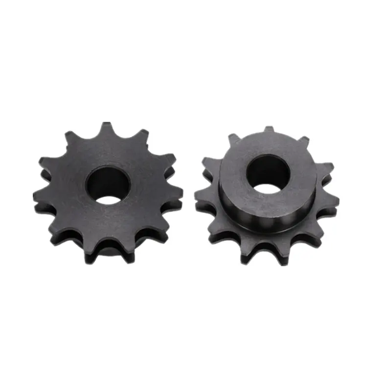
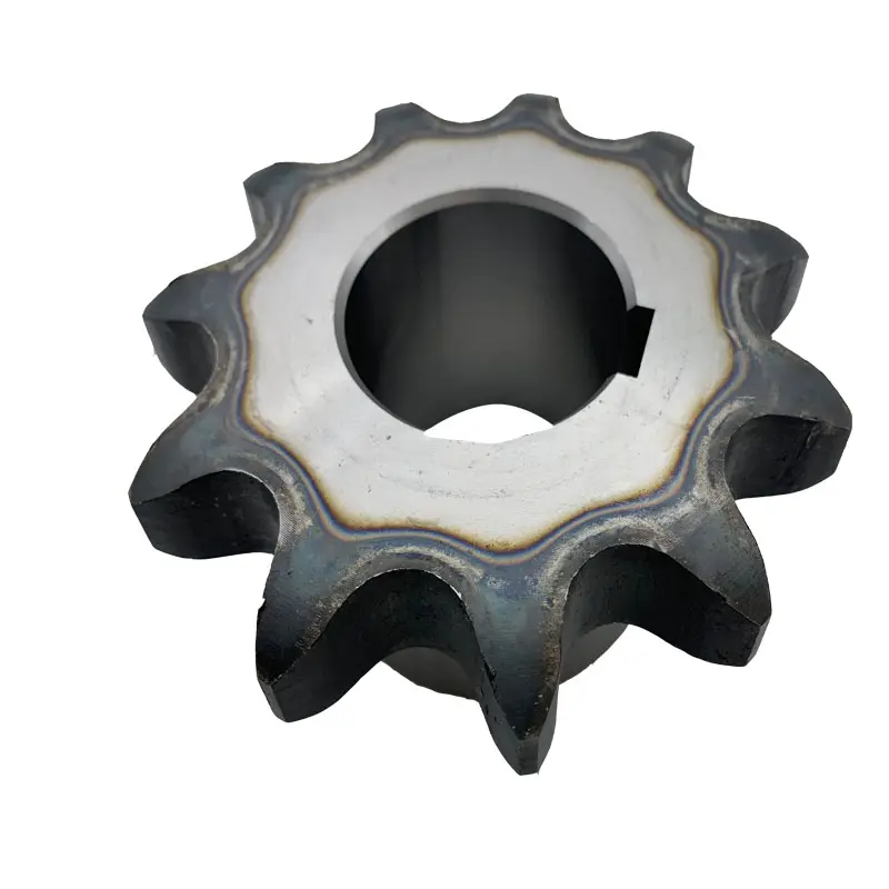
Dozer sprocket chain sprocket drive wheel for CZPT D20 D30 D31 D41-P D50 D53 D60 D65
Pignon
Bulldozer sprocket
Segment
Product Details
| Undercarriage Parts | |
| Name | Sprocket / Segment |
| Material | 50Mn/40MnB |
| Finish | Smooth |
| Colors | Black or yellow |
| Technique | Forging & casting |
| Surface Hardness | HRC48-54 |
| Warranty time | 4000 hours in normal using |
| Certification | ISO9001-9002 |
| MOQ | 2 piece |
| Delivery Time | About 15 days |
| Package | Fumigate seaworthy packing |
Dozer sprocket chain sprocket drive wheel for CZPT D20 D30 D31 D41-P D50 D53 D60 D65
Feature:
1).Lifelong after-sales service.
2).Original /OEM /After Market quality and competitive price-2.Flexible payment terms.
3).Quick delivery time.
Advantages:
1). The parts will give weight,price when quotation.
2). Genuine parts stock pictures will send before order.
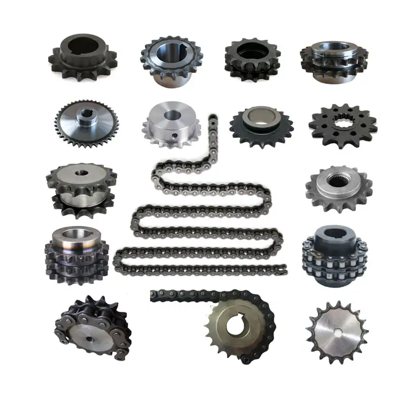
We provide below related product
After-Sales service
1)24 hours for after-sales service;
2)Offer us picture of using situation,goods,using details,then compensation after everything is finished within 3 working days.
3)Any claim due to the quality of products,the compensation is not more than the value of the products that have quality problem.
Packing:standard export fumigated wooden pallet
| Standard ou non standard : | Standard |
|---|---|
| Application: | Excavator & Bulldozer Spare Parts |
| Dureté: | Hardened Tooth Surface |
| Méthode de fabrication : | Forging Casting |
| Forme de la partie dentelée : | Engrenage courbe |
| Matériel: | 35mnb/40mn2 |
| Samples: |
US$ 200/Piece
1 Piece(Min.Order) | |
|---|
| Personnalisation : |
Disponible
| Demande personnalisée |
|---|
wheel sprocket System in Heavy Machinery and Industrial Equipment
Yes, a wheel sprocket system is commonly used in heavy machinery and industrial equipment for power transmission and motion control. The wheel sprocket configuration is a versatile and efficient method of transmitting rotational force between two shafts.
In heavy machinery and industrial equipment, the wheel is typically attached to one shaft, while the sprocket is mounted on another shaft. A chain or a toothed belt is wrapped around the wheel sprocket, connecting them. When the wheel is rotated, the chain or belt engages with the sprocket, causing the sprocket and the connected shaft to rotate as well. This mechanism allows the transfer of power from one shaft to the other, enabling various components and parts of the machinery to function.
Common applications of the wheel sprocket system in heavy machinery include:
- Construction Machinery: Wheel loaders, excavators, cranes, and other construction equipment often use wheel sprocket systems for efficient power transmission in various moving parts.
- Material Handling Equipment: Forklifts, conveyor systems, and other material handling equipment utilize wheel sprocket configurations to move goods and materials smoothly and reliably.
- Mining Equipment: Mining machinery, such as drilling rigs and conveyors, often incorporate wheel sprocket assemblies for power transmission in challenging environments.
- Agricultural Machinery: Tractors, combines, and other agricultural equipment use wheel sprocket systems to drive various components like wheels and harvesting mechanisms.
- Industrial Robotics: Robots and automated systems in manufacturing often utilize wheel sprocket setups for precise motion control and efficient power transmission.
One of the key advantages of the wheel sprocket system is its ability to handle heavy loads and transmit power over long distances. It is a reliable and cost-effective method of power transmission in various industrial settings. However, proper maintenance and alignment are crucial to ensuring the system’s optimal performance and longevity.
Overall, the wheel sprocket system is a widely used and effective power transmission solution in heavy machinery and industrial equipment, offering versatility and efficiency in a range of applications.
Capacités de charge des combinaisons roue-pignon
La capacité de charge d'un ensemble roue-pignon dépend de plusieurs facteurs, notamment du matériau, des dimensions et de la conception des deux pignons. Voici quelques exemples courants d'ensembles roue-pignon et leurs capacités de charge :
- Roue en acier avec pignon en acier : Cette combinaison offre une capacité de charge élevée et est couramment utilisée dans les applications exigeantes. Les roues en acier peuvent supporter des charges importantes et, associées à des pignons en acier, l'ensemble peut résister à des forces encore plus élevées.
- Roue en nylon avec pignon en acier : Les roues en nylon sont réputées pour leur légèreté et leur durabilité. Associées à des pignons en acier, elles offrent une bonne capacité de charge tout en réduisant le poids total de l'ensemble.
- Roue en polyuréthane avec pignon en acier : Les roues en polyuréthane offrent une excellente résistance à l'usure et conviennent aux charges moyennes à élevées. Associées à des pignons en acier, elles peuvent supporter des charges moyennes à élevées.
- Roue en caoutchouc avec pignon en fonte : Les roues en caoutchouc sont réputées pour leurs propriétés d'absorption des chocs et sont souvent utilisées dans les applications nécessitant un amortissement des vibrations. Associées à des pignons en fonte, elles peuvent supporter des charges moyennes.
- Roue en plastique avec pignon en plastique : Cette combinaison convient aux applications légères où les charges prévues sont faibles. Les roues et pignons en plastique sont souvent utilisés dans les applications exigeant un faible frottement et un fonctionnement silencieux.
- Combinaisons de pignons de roue personnalisées : Dans certains cas, des combinaisons roue-pignon sur mesure sont conçues pour répondre à des exigences de charge spécifiques. Ces combinaisons peuvent être adaptées aux besoins uniques de l'application.
Il est important de noter que la capacité de charge dépend également d'autres facteurs, tels que le type de roulement utilisé dans la roue, le matériau de l'arbre et la conception globale du système mécanique. Les ingénieurs doivent examiner attentivement l'application prévue, les conditions de fonctionnement et les facteurs de sécurité lors du choix de la combinaison roue-pignon appropriée afin de garantir des performances optimales et une longue durée de vie au système.
Calculating Gear Ratio for a wheel sprocket Setup
In a wheel sprocket system, the gear ratio represents the relationship between the number of teeth on the sprocket and the number of teeth on the wheel. The gear ratio determines the speed and torque relationship between the two components. To calculate the gear ratio, use the following formula:
Gear Ratio = Number of Teeth on Sprocket ÷ Number of Teeth on Wheel
For example, if the sprocket has 20 teeth and the wheel has 60 teeth, the gear ratio would be:
Gear Ratio = 20 ÷ 60 = 1/3
The gear ratio can also be expressed as a decimal or percentage. In the above example, the gear ratio can be expressed as 0.3333 or 33.33%.
It’s important to note that the gear ratio affects the rotational speed and torque of the wheel sprocket. A gear ratio greater than 1 indicates that the sprocket’s speed is higher than the wheel’s speed, resulting in increased rotational speed and reduced torque at the wheel. Conversely, a gear ratio less than 1 indicates that the sprocket’s speed is lower than the wheel’s speed, resulting in decreased rotational speed and increased torque at the wheel.
The gear ratio is crucial in various applications where precise control of speed and torque is required, such as bicycles, automobiles, and industrial machinery.


editor by CX 2023-08-31


