Описание продукта
Описание продукта
| Material: | 45#Steel,20CrMnTi,40Cr,20CrNiMo,20MnCr5,GCR15SiMn,42CrMo,2Cr13stainless steel,Nylon,Bakelite,Copper,Aluminium.etc |
| Process: | The main process is Gear Hobbing, Gear Shaping and Gear Grinding, Selecting production process according to the different products. |
| Heat Treatmente: | Carburizing and quenching ,High-frequency quenching,Nitriding, Hardening and tempering, Selecting heat treatment according to the different materials. |
| Testing Equipment | Rockwell hardness tester 500RA,
Double mesh instrument HD-200B & 3102, Gear measurement center instrument CNC3906T other High precision detection equipments |
| Certification | 0.1-90 kg |
| Casting Size: | Max linear size: 1200 mm, Max diameter size: 600 mm |
| Machining tolerace: | GB/T19001-2016/ISO9001:2015 |
| Machining surface roughness: | Ra0.8 ~ 6.3 um |
| Material standard: | GB, ASTM, AISI, DIN, BS, JIS, NF, AS, AAR |
| Usage: | Used in printing machine, cleaning machine, medical equipment, garden machine, construction machine, electric car, valve, forklift, transportation equipment and various gear reducers.etc |
| Quality control: | 100% inspection before packing |
| Manufacture Standard | 5-8 Grade ISO1328-1997. |
Company Profile
SIMIS CASTING, established in year of 2004, is a professional foundry, including integrating development and production together, specialized in producing various kinds of investment casting parts, and CZPT parts and forging parts. These casting and forging parts are widely used in automobile industry, railway vehicle, construction machine, municipal works, pipeline, petrochemical industry, mine, electric utility industry and so on.
SIMIS has 6 affiliated casting workshop and 2 professional CNC machining workshops. There are 500 staffs and 40 engineers now in our company. Its annual production capacity for all types of casting parts is about 3000 tons. Holding over 100 sets of advanced casting parts, machining and test equipments.
Gear including planetary gear, spiral gear, bevel gear, spiral bevel gear, helical gear, spur gear, helical spur gear, conical gear, CZPT pinion gear, conical CZPT and bevel gear, worm gear and shaft, we can make standard thickness gear 1 to 8 Module, 1M12, 2M20, 2.5M25, 3M30, 4M40, 5M50, 6M60, 8M80. Non-standard thickness 2 to 8 Module: 2M16, 2.5M20, 3M20, 4M30, 4M35, 5M40, 5M30, 6M40, 6M50, 8M60. We can also make customized gear according to your drawing or sample.
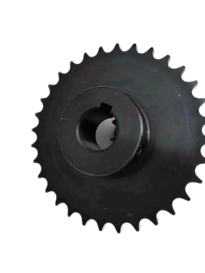
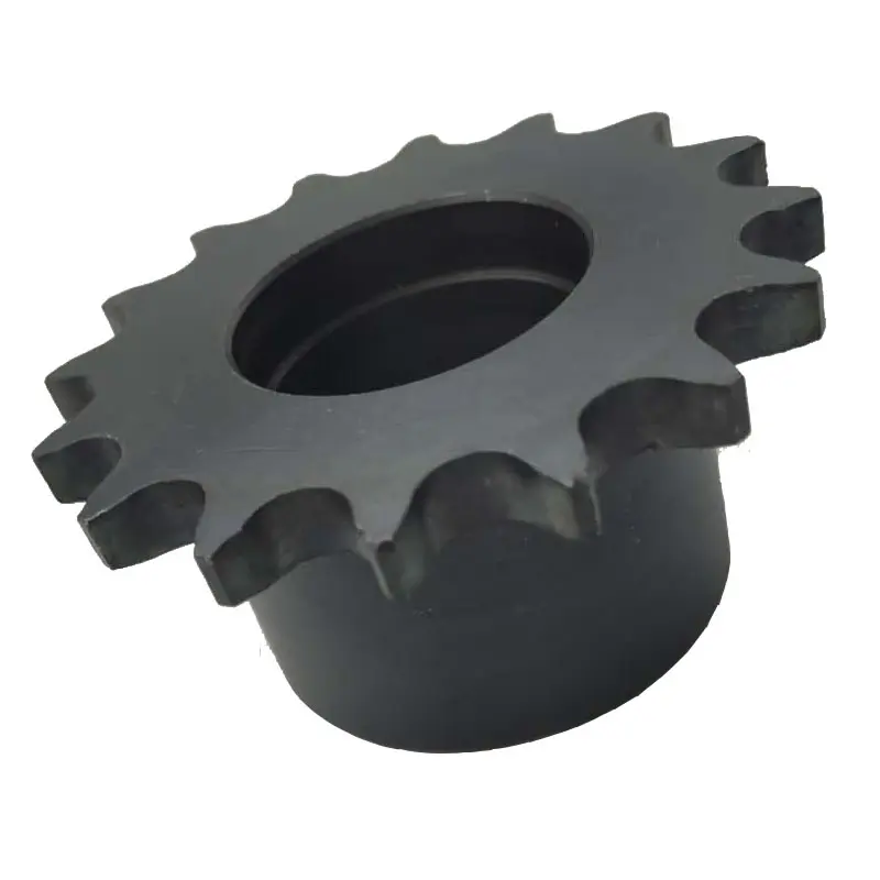
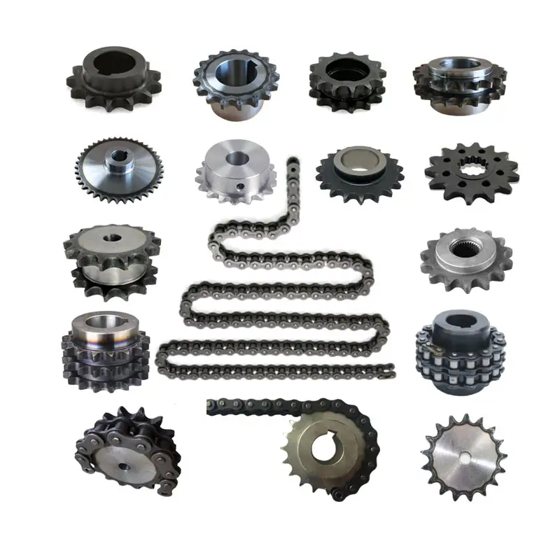
Звездочка including simplex sprocket, duplex sprocket, triplex sprocket, and has 45 steel finished hole sprocket, 06B 06C 08A 08B 08C 10A 12A 16A 24A sprocket and so on.We can also make customized gear according to your drawing or sample too.
Welcome you come to visit us for customized various types of non-standard gear, sprocket synchronous wheel, helical gear, bevel gear, shaft, worm gear and other products with the lowest quality!
Application Field
Testing Ability
| Dimensional | Non-Destructive Tests(N.D.T.) | Chemical & Mechanical |
| Surface Roughness Test | Dye Penetrant | Chemical analysis |
| Microscopic Measurement | Radiography (RT) | Metallography |
| 3D ScHangZhou | Magnetic Particle (MT) | Tensile Strength |
| CMM | Ultra-Sonic (UT) | Yield Strength |
| Impact Test | Hardness Test | Elongation Rate |
| Shrinkage Rate |
Часто задаваемые вопросы
Q1:Are you manufactory or trade company?
A1:We are an enterprise integrating manufacturer and trade for many years already in ZheJiang province, China. And we are AAA grade credit enterprise, and also we have cooperative plants to provide other services such as plating and coating .
Q2: How could I get a free quotation?
A2:Please send us your drawings by Alibaba or email. The file format is PDF / DWG / STP / STEP / IGS and etc. IF there are no drawings, we can make the drawings according to your samples!
Q3:How to control quality?
A3:First, all raw materials are inspected by the quality control department before they are put into storage. Second, during the casting process, 3 times of spectral analysis were performed at the front, middle and back respectively. Third, after the parts are cleaned, perform a first visual inspection to check whether the product has casting defects before sending it to the next process. Fourth, conduct a comprehensive QC inspection of each part before shipment, including chemical composition, mechanical properties and other specific tests. Transactions can be through Alibaba’s trade assurance.
Q4:Can we have our Logo or company name to be printed on your products or package?
A4:Sure. Your Logo could be printed on your products by Hot Stamping, Printing, Embossing, UV Coating, Silk-screen Printing or Sticker.
| Стандартный или нестандартный: | Nonstandard |
|---|---|
| Приложение: | Motor, Electric Cars, Motorcycle, Machinery, Marine, Agricultural Machinery, Car, Rolling Sprocket |
| Твердость: | Затвердевшая поверхность зуба |
| Образцы: |
US$ 5/Piece
1 штука (минимальный заказ) | Заказать образец |
|---|
| Настройка: |
Доступный
| Индивидуальный запрос |
|---|
.shipping-cost-tm .tm-status-off{background: none;padding:0;color: #1470cc}
|
Стоимость доставки:
Ориентировочная стоимость доставки за единицу товара. |
о стоимости доставки и предполагаемом времени доставки. |
|---|
| Способ оплаты: |
|
|---|---|
|
Первоначальный платеж Полная оплата |
| Валюта: | US$ |
|---|
| Возврат и возмещение средств: | Вы можете подать заявку на возврат средств в течение 30 дней после получения товаров. |
|---|
Расчет требуемого крутящего момента для сборки звездочки колеса
Расчет требуемого крутящего момента для звездочки колеса включает в себя учет различных факторов, влияющих на нагрузку. Требуемый крутящий момент имеет решающее значение для выбора подходящего двигателя или источника питания для эффективного привода системы. Вот пошаговая инструкция:
- 1. Определите момент нагрузки: Определите крутящий момент, необходимый для преодоления сопротивления или нагрузки в системе. Это включает в себя крутящий момент, необходимый для перемещения нагрузки, преодоления трения и, если применимо, ускорения нагрузки.
- 2. Определите радиус звездочки: Измерьте радиус звездочки (расстояние от центра звездочки до точки контакта с цепью или ремнем).
- 3. Рассчитайте натяжение цепи или ремня: При использовании цепной или ременной передачи рассчитайте натяжение цепи или ремня. Натяжение влияет на крутящий момент, необходимый для передачи мощности.
- 4. Учитывайте потери эффективности: Учитывайте эффективность системы. Не вся входная мощность будет преобразована в выходную из-за трения и других потерь. Учитывайте этот фактор в своих расчетах.
- 5. Используйте уравнение крутящего момента: Крутящий момент (T) можно рассчитать по следующей формуле:
T = (Крутящий момент нагрузки × Радиус звездочки) ÷ (КПД × Натяжение)
Для всех значений в уравнении крайне важно использовать согласованные единицы измерения (например, ньютон-метры или фут-фунты).
Помните, что реальные условия могут отличаться, и рекомендуется добавить запас прочности к расчетным требованиям к крутящему моменту, чтобы гарантировать, что система сможет выдерживать неожиданные пиковые нагрузки или изменения условий эксплуатации.
Using wheel sprocket Assembly in Robotics and Automation
Yes, wheel sprocket assemblies are commonly used in robotics and automation systems to transmit power and facilitate movement. These systems offer several advantages for robotic applications:
- Efficiency: wheel sprocket assemblies provide efficient power transmission, ensuring smooth and precise movement of robotic components.
- Compact Design: The compact nature of sprockets and wheels allows for space-saving designs, making them ideal for robotic applications where space is limited.
- Precision: Sprockets and wheels with accurate teeth profiles provide precise motion control, crucial for robotics and automation tasks that require high levels of accuracy.
- Low Noise: Properly lubricated and maintained wheel sprocket systems generate minimal noise during operation, contributing to quieter robotic movements.
- Customizability: wheel sprocket assemblies can be customized to suit specific robotic requirements, such as different gear ratios, sizes, and materials.
- Multiple Configurations: Depending on the robotic application, different configurations like single or multiple sprockets, idler sprockets, or rack and pinion systems can be used.
- High Load Capacity: Sprockets made from durable materials like steel can handle substantial loads, making them suitable for heavy-duty robotic tasks.
Examples of robotics and automation systems that commonly use wheel sprocket assemblies include:
- Robotic Arms: wheel sprocket systems are utilized in robotic arms to control their movement and reach.
- Automated Guided Vehicles (AGVs): AGVs use wheel sprocket assemblies for propulsion and steering, enabling them to navigate autonomously.
- Conveyor Systems: In automated factories, conveyor belts are often driven by sprockets and wheels for efficient material handling.
- Mobile Robots: Wheeled mobile robots use wheel sprocket assemblies to drive their wheels, enabling them to move in various directions.
- Robot Grippers: wheel sprocket mechanisms can be integrated into robot grippers to facilitate gripping and handling objects.
The choice to use wheel sprocket assemblies in robotics and automation depends on the specific application requirements, load capacity, precision, and environmental conditions. By selecting the appropriate sprockets, wheels, and materials, engineers can ensure reliable and efficient robotic performance in a wide range of automated tasks.
Calculating Gear Ratio for a wheel sprocket Setup
In a wheel sprocket system, the gear ratio represents the relationship between the number of teeth on the sprocket and the number of teeth on the wheel. The gear ratio determines the speed and torque relationship between the two components. To calculate the gear ratio, use the following formula:
Gear Ratio = Number of Teeth on Sprocket ÷ Number of Teeth on Wheel
For example, if the sprocket has 20 teeth and the wheel has 60 teeth, the gear ratio would be:
Gear Ratio = 20 ÷ 60 = 1/3
The gear ratio can also be expressed as a decimal or percentage. In the above example, the gear ratio can be expressed as 0.3333 or 33.33%.
It’s important to note that the gear ratio affects the rotational speed and torque of the wheel sprocket. A gear ratio greater than 1 indicates that the sprocket’s speed is higher than the wheel’s speed, resulting in increased rotational speed and reduced torque at the wheel. Conversely, a gear ratio less than 1 indicates that the sprocket’s speed is lower than the wheel’s speed, resulting in decreased rotational speed and increased torque at the wheel.
The gear ratio is crucial in various applications where precise control of speed and torque is required, such as bicycles, automobiles, and industrial machinery.


editor by CX 2023-11-07


