Professional Wheel Sprocket Manufacturer & Supplier
ANSI · ISO · JIS · DIN · BS Standards. Induction-hardened teeth, precision machining, and full custom engineering support — backed by ISO 9001 quality assurance.
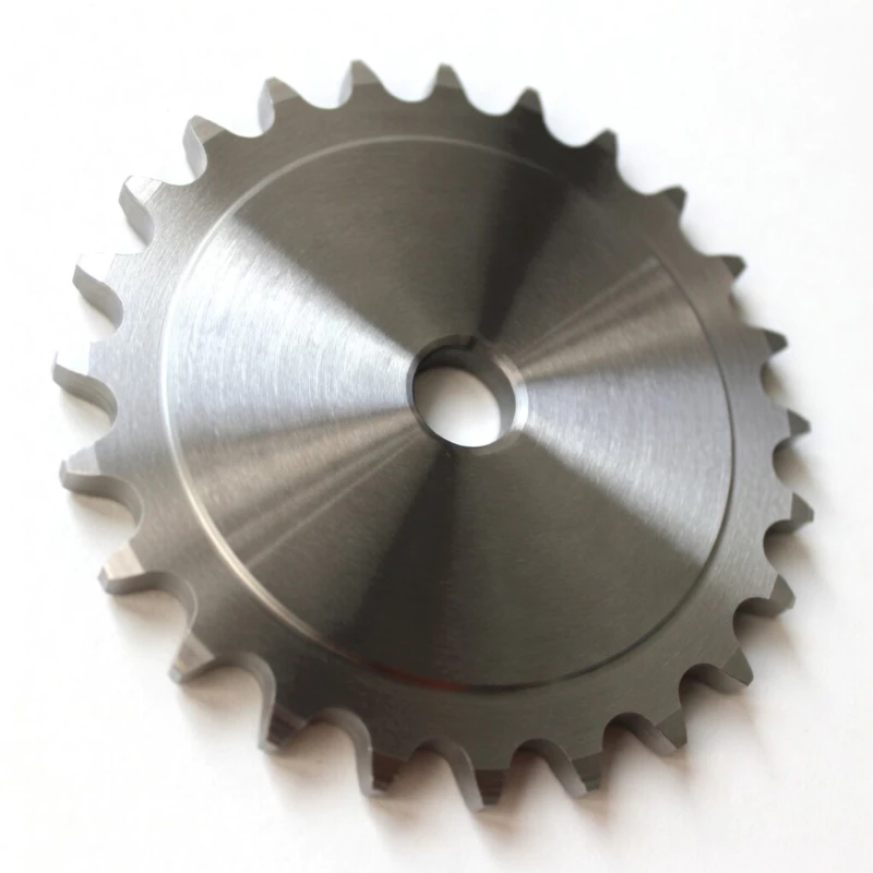
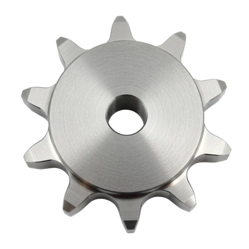
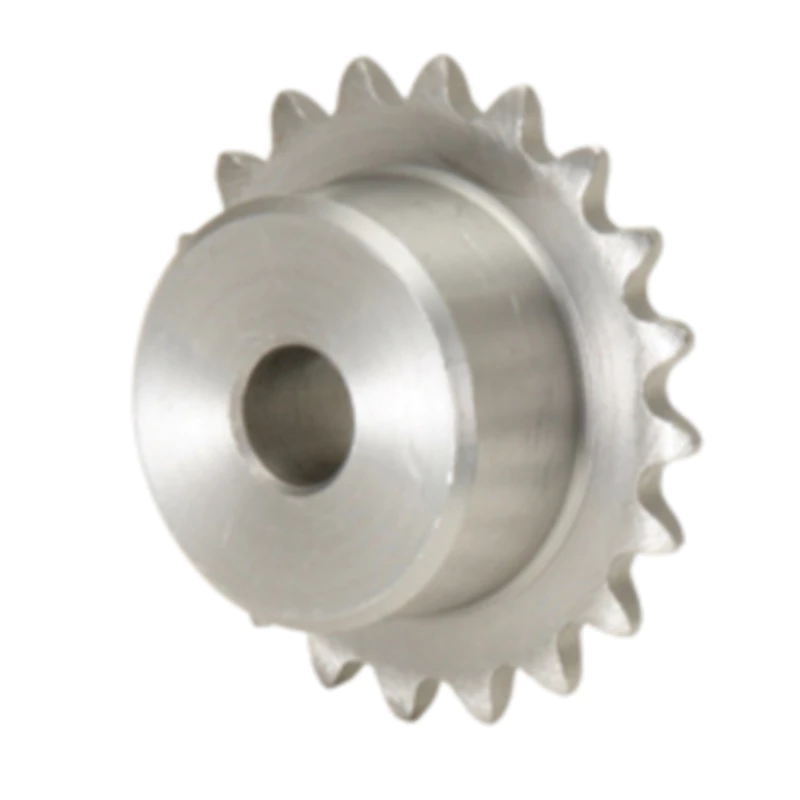
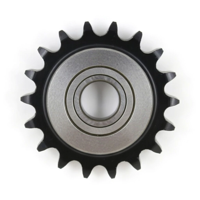
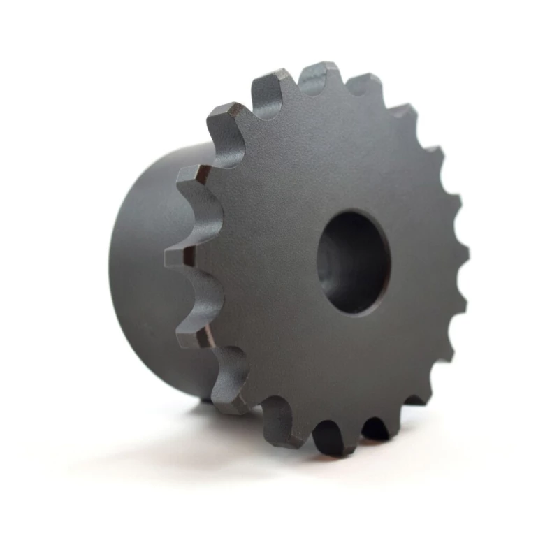
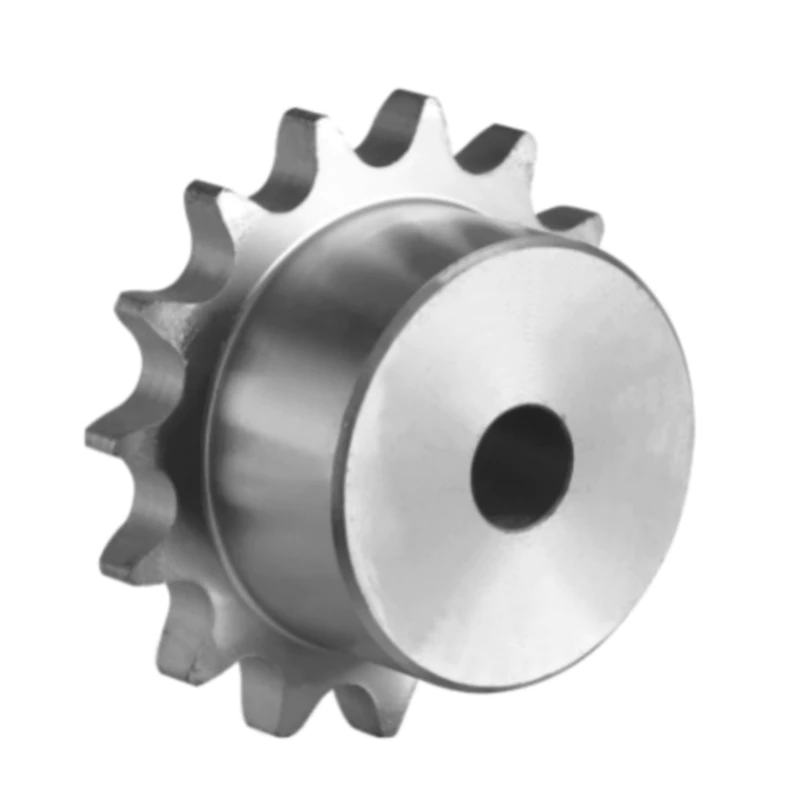
Wheel Sprocket Product Categories
From standard and metric sprockets to custom-engineered solutions — we manufacture the full range for Australian industry.


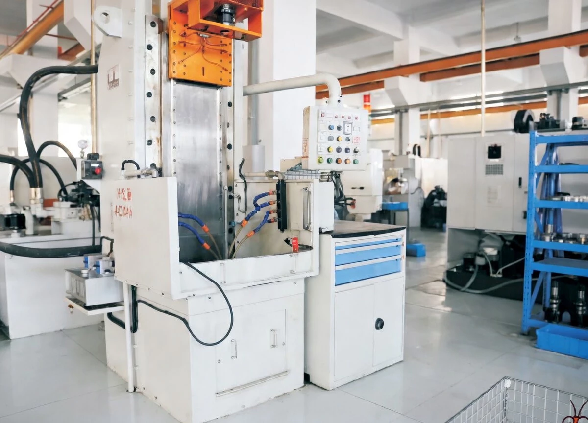
Manufacturing Capability & Quality Assurance
Every sprocket we supply to Australia is built to a standard that exceeds what the market demands — here is why engineers trust Ever-power.
Wheel Sprocket Applications Across Australian Industry
Our sprockets operate across virtually every sector of Australian heavy industry — built to perform in the harshest real-world conditions.

Integrated Manufacturing, Research & Export
Ever-power Australia Wheel Sprockets is a modern enterprise combining chain drive research, precision manufacturing, and international trade. Our products serve customers throughout Australia and are manufactured to GB, ISO, ANSI, JIS, DIN and BS standards — ensuring cross-compatibility and engineering confidence.
From our purpose-built factory, we supply sprockets for some of Australia’s most demanding industrial environments — from outback mining to food processing facilities on the east coast. Every batch undergoes rigorous in-house quality testing before delivery. Explore our full product range →
Supply your drawings, samples or specifications — we will engineer and manufacture to your exact requirements with rapid prototyping and competitive pricing for the Australian market.
Whether you need a standard replacement sprocket or a complex custom-engineered drive component, our Australian sales team is ready to assist. Fill in the form and we will get back to you as soon as possible.
-
Email Us
[email protected] -
Online Enquiry
wheelsprocket.xyz/contact-us -
Custom Manufacturing
Supply drawings or samples for rapid prototyping and pricing -
Browse Full Range
Explore all wheel sprocket categories


